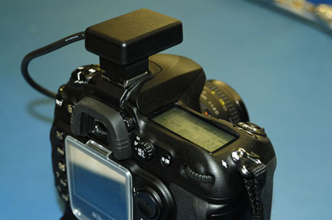
The camera does not send any serial data to the GPS. Thus only the TX line from the GPS need be connected. The camera's serial interface is 5V TTL - and appears to have a higher than average threshold making direct interfacing with 3.3V TTL somewhat difficult (I ended up using a very low power 1-bit level converter). The camera outputs 5V - this is how accessories like the MC35's (Nikon's off the shelf serial interface cable) TTL to RS232 level converter are powered - and how I will power the GPS receiver presented here. When GPS NMEA strings are presented to the camera - the camera does not power down its meter as you typically see if the camera is powered up but no buttons are touched for a short time. While the GPS receiver draws power from the camera - having the meter always on contributes to the power consumption. On the other hand, the camera is always hot and primed with the most recent GPS point position ready to capture an image.
I had previously build a prototype using almost the same components, but to get the size down, I needed to create a PCB that fit in my target enclosure. This allowed me to use even smaller surface mount components, and made the assembly much easier. So I laid out a board and had it fabed - this is probably the only component of my solution that can't be purcased off the shelf. If interest is high enough, I could maybe do a larger quantity run of these boards and sell them to folks wanting to build this solution exectly.
Feel free to email me with questions on this soltuion and I will do my best to answer. I work with GPS (both embedded and survey/geodedic) every day, so I suspect I am taking some things for granted that might not otherwise be clear. I will try to accumulate questions and answers in an FAQ at the end of this page.
My Design goals:
As small as possible, low component count
Very low power
Fast sv acquisition and reacquisition - balance with power consumption
GPS with Good sensitivity
No separate LNA required
Maintains lock in any camera orientation once tracking
GPS that does not require battery backup to maintain a config
GPS that can be configured with I/O pins
Clean exterior - no LEDs or switches
Camera powered
Optional: a way to have a remote release passthrough
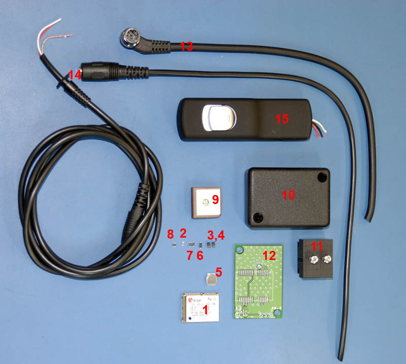
Here is an image of all the parts I use for assembly - including an aftermarket
release and new 2.5mm cable/plug/socket for the release interface:
ASSEMBLY
Here are the assembly steps:
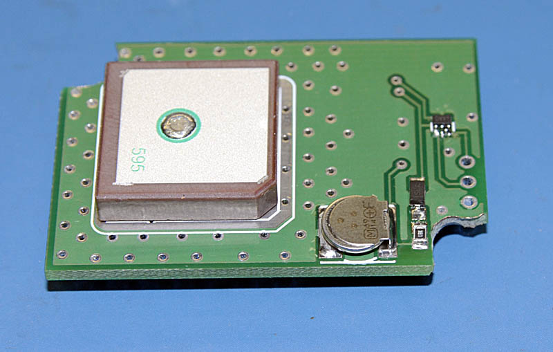
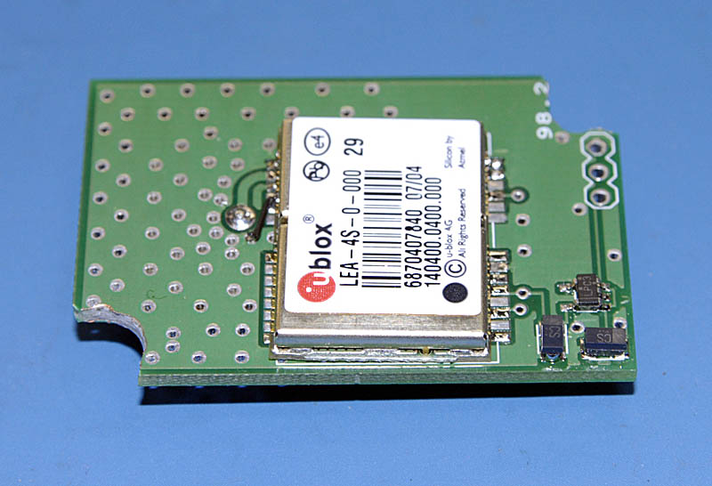
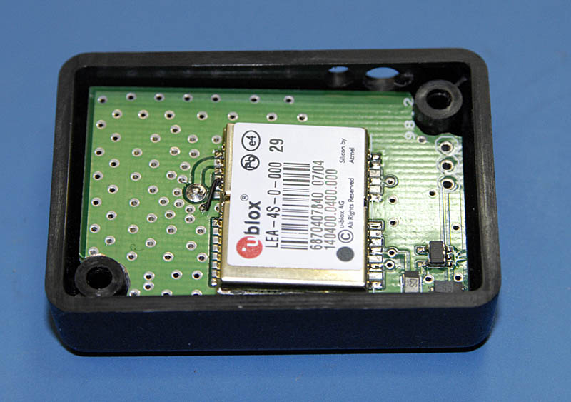
1. I start by using a dremel tool to mill back the two corners of the PCB so it will fit into the enclosure (see the images below of the PCB with components).
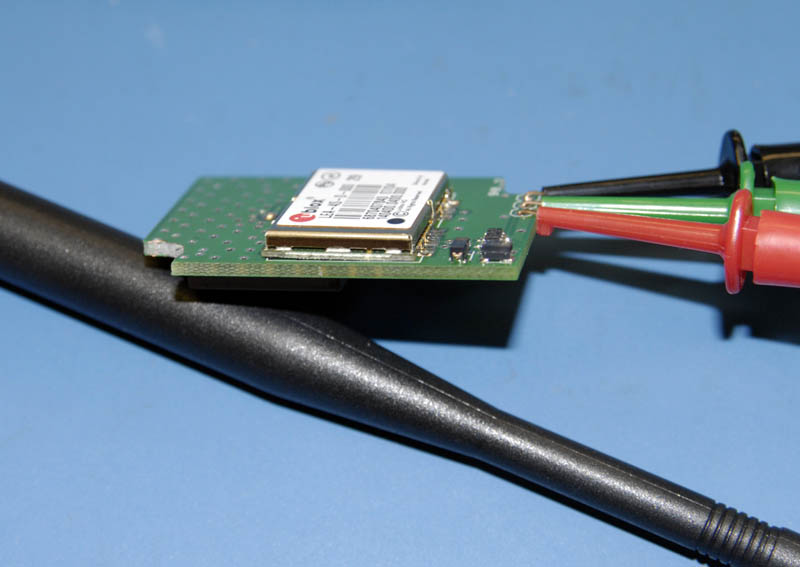
2. I populate the inexpensive components (everything but the GPS and antenna) and apply power (5V DC just as the camera will) and use a volt meter or scope to test if the voltage regulator is working and power is present on the pads where I expect.
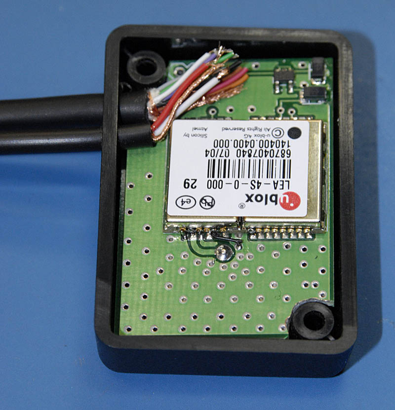
3. Populate the GPS receiver and antenna. You can see on the second image below that my first PCB had a mistake that I fixed with a short wire...also that on this particular build I did not do a very good job getting the GPS on straight.
4. Power up (with 5V DC) and confirm that the GPS is outputting NMEA strings at 4800 baud. (See Testing below)
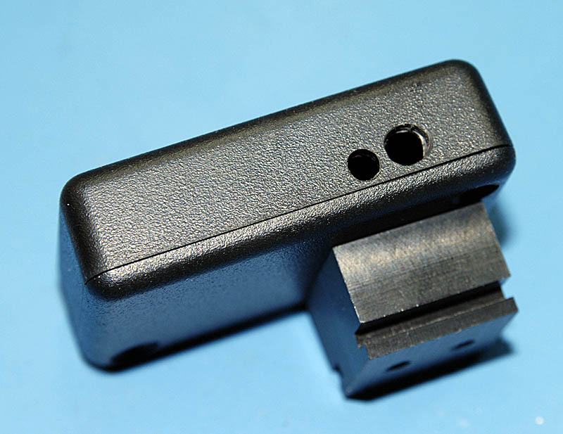
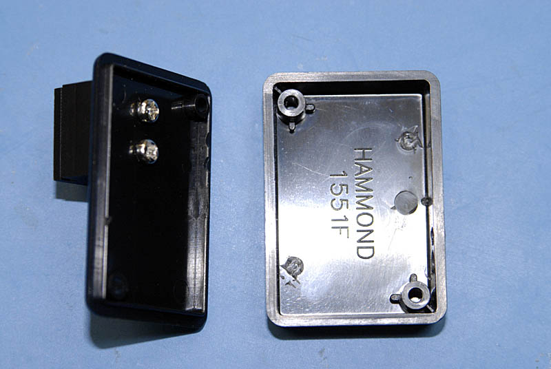
5. Prepare Enclosure. Next I drill holes in the enclosure and attach the hot-shoe mount. I found this mount from The B.E.C. Group - but I was told that it is soon to be discontinued - which is a bummer because I think it fits this application perfectly...in fact I may go buy a few extra just to have. You can create whatever mounting scheme works best for you - for me, the hotshoe was just find, and it keep the GPS antenna pointed in the optimal direction most of the time. NOTE - that in addition to drilling the holes in the side of the enclosure, I had to snip off some platic posts inside the enclosure to make more room available. Note that I have drilled a hole for the cable with the 2.5mm jack to allow for remote release passthrough - if you don't need the remote release, you can simply leave it off.
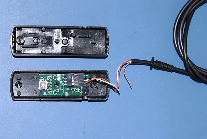
6. The rest is mostly mechanical and hooking up the interface wires. On this build I have added a passthrough for a remote shutter release. The release is optional - it depends on your needs. For GPS operation, only three of the 10 signals on the 10-pin cable need to be connected: PWR, GND, and RXD. If the remote release passthrough is used, another three signals are connected (one common ground and two signals from one cable to the other) - the signal to trigger autofocus/meter and the signal to release the shutter.
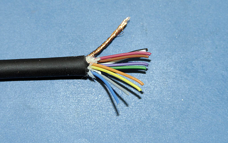
I found the excellent diagram below sometime back from someone else's site and I can no longer find the source. If this is your graphic below, please let me know and will remove it and insert a link to the origial. The diagram shows the pinout for the 10-pin connector, the signals on each of the wires (these colors are likely only valid with Nikon factory cables) and the state of each of the signals for different camera modes.
----> Still working on this part. I plan to include a table showing wiring connections and discussion of how the remote release is wired. Also images of the final product and how the cable release plugs into the 2.5mm jack. <-------
TESTING
Testing for GPS operation and output
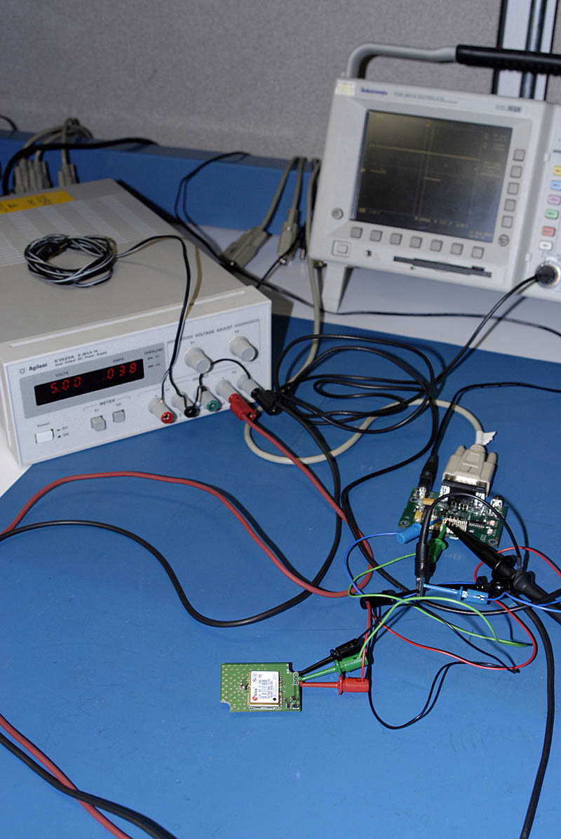
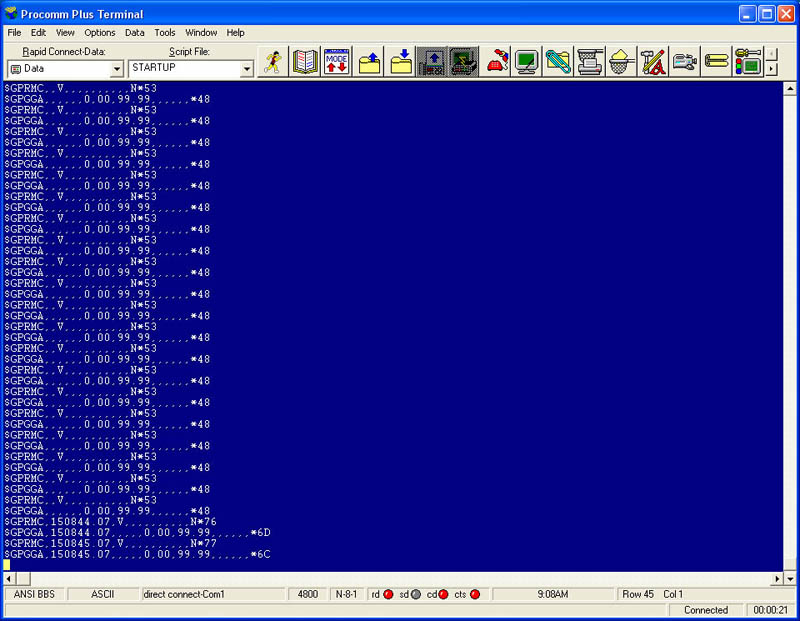
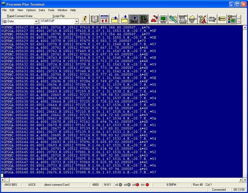
To do this I used a TTL to RS232 converter board I already had and hooked up the output of the GPS board to the RX on the converter. The converter was then connected to a PC running a terminal program (in this case Procomm) at 4800 Baud. One should see just the GGA and RMC strings. Because the GPS receiver is indoors without any skyview, and is new from the factory without any almanac/ephemeris, the GGA and RMC strings are empty. Once the unit begins tracking, data will be filled in. See Testing Tracking below.
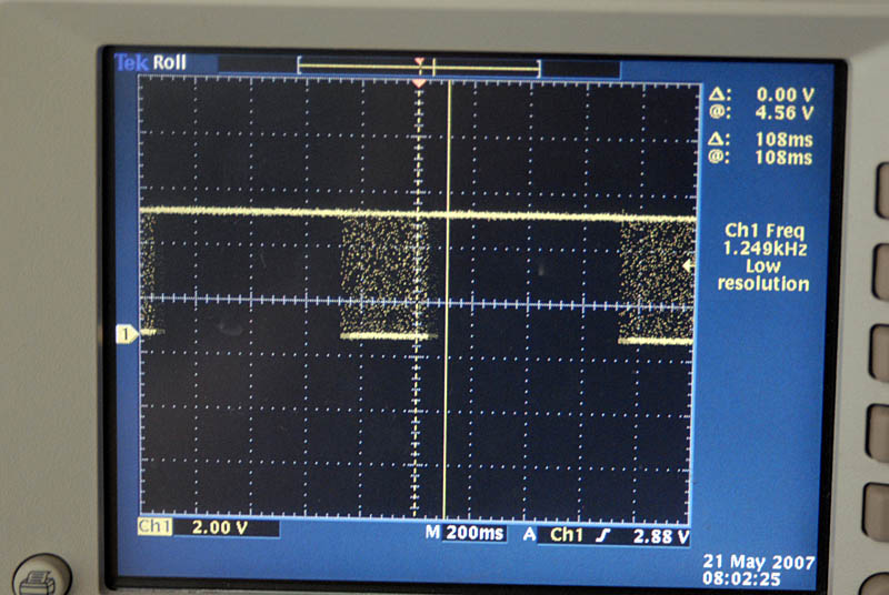
Those with a scope can confirm the output - in this case we see a burst of NMEA data every second.
Testing for GPS Tracking
After confirming that the GPS is basically operational, I test to confirm that it can track. This is best done when the GPS antenna has some view of the sky. I actually have an antenna on the roof and a splitter. I simply connected an antenna (in this case it wasn't even a GPS antenna - it might as well have been a piece of wire) to the end of one of the splitter outputs and placed it near the receiver's antenna.
Given that this is the first time this GPS receiver has tracked since the factory, it might take a few moments to acquire. Soon the NMEA output on the terminal application shows it tracking.
SUMMARY
The unit actually performs better than I had expected. The GPS receiver is so sensitive, that once it is tracking it really stays locked unless the signals are really obscured. Power consumption is very low (~35ma at 5VDC once tracking). Acquisition time (~45-60 seconds) and reacquisition time (0-5 seconds) are fast. One item I would like to improve is the supercap and how long the GPS receiver stays "hot" after power is removed. Right now, if the camera is switched off for a short period (0-20 min) the reacquisition is very fast, after approximately that amount of time the GPS receiver starts "warm" or "cold" and takes ~45 seconds to lock. The supercap discharges too quickly and I am looking for a way to improve this without going to a battery to a too much larger supercap.
FAQ
Coming soon....I will compile questions and answers and post them here.